A ASME diagram It can be a great alternative to depict the activities graphically that make up a process. Here is all the information.
It's really useful for people who need to develop or carry out a process consisting of several steps, since those steps are illustrated here in detail.
How do you create an ASME diagram?
It's important to know What are all the steps? that make up this graphic format.
1. Receipt of Materials
These types of diagrams always start with the receipt of materials. It is represented by a horizontal line. All the characteristics of the material must be listed there. For example, 15 kilograms of flour.
2. Activity Symbols
Now, it's worth mentioning the symbols representing the process activities. To do this, a vertical line pointing downward is added to a horizontal line, which represents the material input.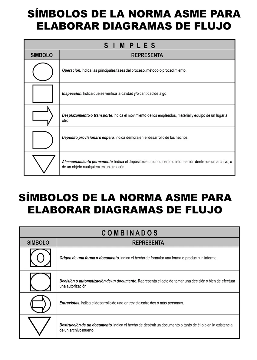
ASME Symbols. Source: wimservices.wixsite
3. Ensemble
Here, you may need a material to continue with, so the entry needs to be clarified.
-
- There may be a purchased materials, so we need to draw a horizontal line to the left of the vertical line.
- However, if it is processed internally, at the very beginning of the process, this needs to be clarified.
4. Component with the most activities
In this step, you need to to clear a main line, which corresponds to the most important part of the process or product, since it includes the largest number of activities.
5. Operation
When materials come in, we need specify an operation, but no other activity. So, in this case, the following operation is mentioned.
6. Disassembly
The Product is broken down into its components, so we need to chart a material outflow that occurs after the disassembly operation. This is done using a horizontal line which is located to the right of the flow lines. Therefore, this line lists the smallest parts of the disassembled material.
For larger materials, the process continues along the vertical line. If the disassembled material is not reintegrated into the production process, only a horizontal line is drawn to the right, and the process continues along the vertical line. If it is reintegrated, the disassembly process must appear to the right of the vertical line.
7. Intersection
In the event that there is a intersection within the flow line, you have to draw a semicircle inside the intersection.
8. Acceptances and Rejections
This is where they are likely to occur products that require no additional work, which must be to the right of the vertical flow line. If they are rejected, they will be to the left.
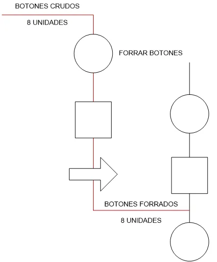
ASME Flow Acceptances and Rejections. Source: industrialengineeringonline
9. Unit Conversions
As we come to the end, if there is a change in the production unit, the following are included two horizontal lines in the unit where there is an interruption in the flow.
10. Numbering
Finally, it is necessary to list the operations and all the materials. You always start with the main line, in order of appearance.
This process could be key for all companies engaged in product manufacturing. That is why it is important to note that Structuralia It is a school that enables professionals to acquire the essential knowledge for this field. For example, there are various training courses that can be useful for creating this diagram, such as our Specialized master's degrees in industry and construction.
Now you know the steps to take to perform a ASME diagram. We hope this information has been helpful for all your projects, as it will help you visualize all the necessary details graphically.