
The BIM methodologies show different benefits in the development of construction projects. This interesting master's thesis explains it to us.
Master's Thesis Project: BIM in Commercial Buildings
A project completed after earning a Master's degree in BIM Applied to Building Construction, which draws on based on the preliminary design for a supermarket located in Uruguay, carried out by another architect who designed the masonry and plumbing, as well as the various structural, electrical, and HVAC consultants, under CAD methodologies.
Among these, the focus is on the «Modeling» from various disciplines, based on a preliminary design developed using CAD methodologies, which will lead to greater efficiency by allowing the project to continue to be developed using BIM methodologies, the «Coordination» of those disciplines, as well as the «Information Management» not only for the design phase, but also with a view to future uses such as construction and the subsequent operation and maintenance, as well as the «Photorealistic rendering of the project.».
Modeling
To simulate collaborative work, in this case, we used one model for each discipline, simulating how the work would have been carried out if we had worked with the advisors. using BIM methodologies.
Among the models created are those from the disciplines of Structure, Masonry, Sanitary, Electrical y HVAC, as well as a coordination file containing the linked files from the various disciplines; from this file, data will be exported to various software programs, such as TWINMOTION, the connection to NAVISWORKis carried out based on the models of each discipline, as follows makes it easier to organize collision detection.
Another option would be to work on a single model that combines several or all of the disciplines, but dividing it into subprojects, with each subproject handled by a different person.
Several people can also work on the same subproject, but it can be more cumbersome if not organized properly, since when one user edits an element or view, it becomes locked for that user, and the other user working on the project will not be able to edit it until the first user grants permission to do so. In addition, special care must be taken to release all elements before stopping work on the project.
1. Structure
The modeling work was done entirely in Revit, although the Organization had originally planned to hold it in Tekla, since it was another piece of software we studied in the master's program, and the student license had already expired, so I decided to do it in Revit.
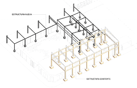
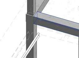
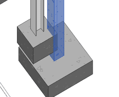
Although collision detection is performed using NAVISWORK, during the modeling process, it is normal to encounter details that need to be resolved or inconsistencies in the CAD drawings, between floor plans and elevations, for example, as well as the 3D visualization It helps quickly identify areas that need to be defined, such as likely existing foundations near the new foundations.
2. Masonry
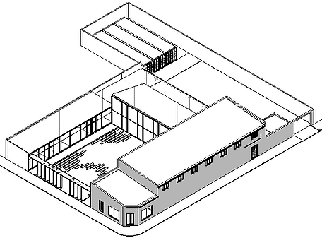
The Masonry Model is not overly complex; it is a small-to-medium-scale project, which was recommended given the approximately one-and-a-half-month timeframe available to complete the master’s thesis, in which students were required to develop at least one additional discipline besides masonry, and use various software programs to complete it.
3. Sanitation
In the Sanitary Modeling Process, Not all dimensions were available—only the slopes and some footing dimensions for certain chambers— which is normal for the preliminary design phase. Combined with the fact that traditional CAD drawings often do not take into account the actual dimensions of the various components, modeling brings the project to a much higher level of detail and resolves some interferences on the spot.
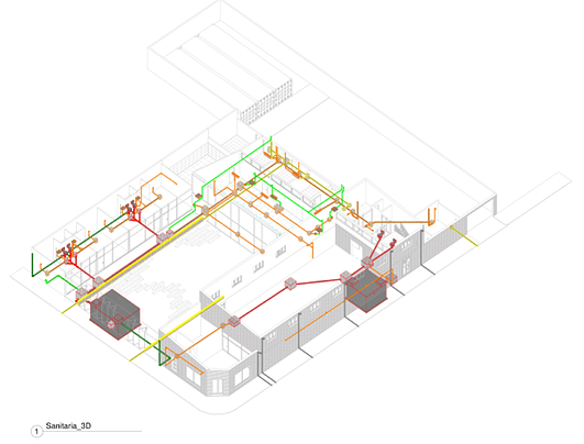
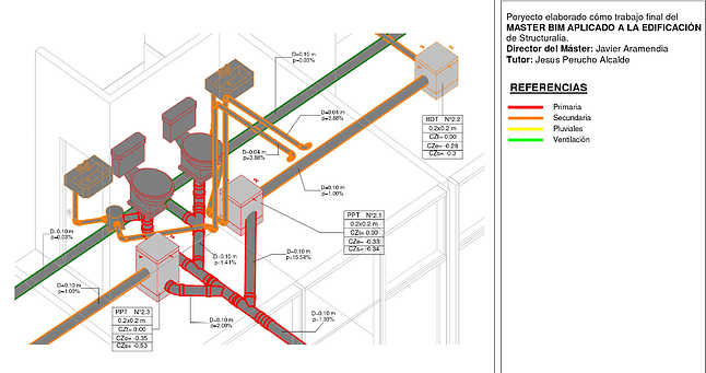
The MEP models They can be loaded with a lot of information to make them smarter. In this case, for example, the septic tank was modeled to maintain a set volume of 2,000 liters by increasing its depth as the depth of the inlet water level increases, in a parametric manner.
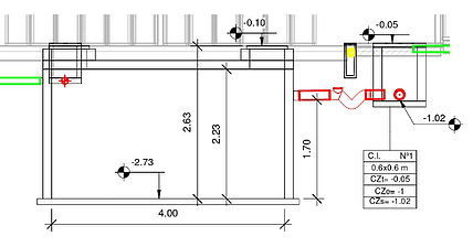
In the case of the cameras, it was decided to remove the MEP connectors to allow the pipes to be routed in any direction.
5. Electrical
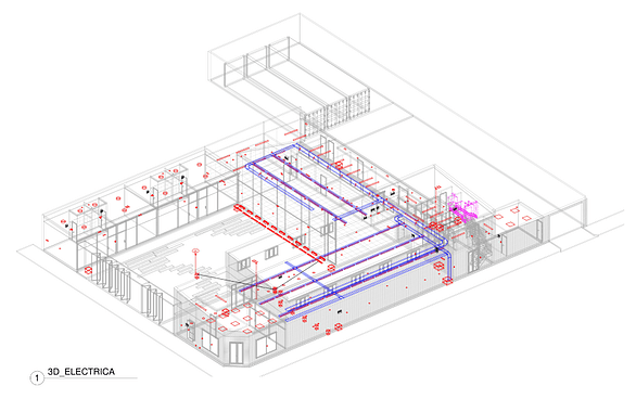
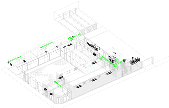
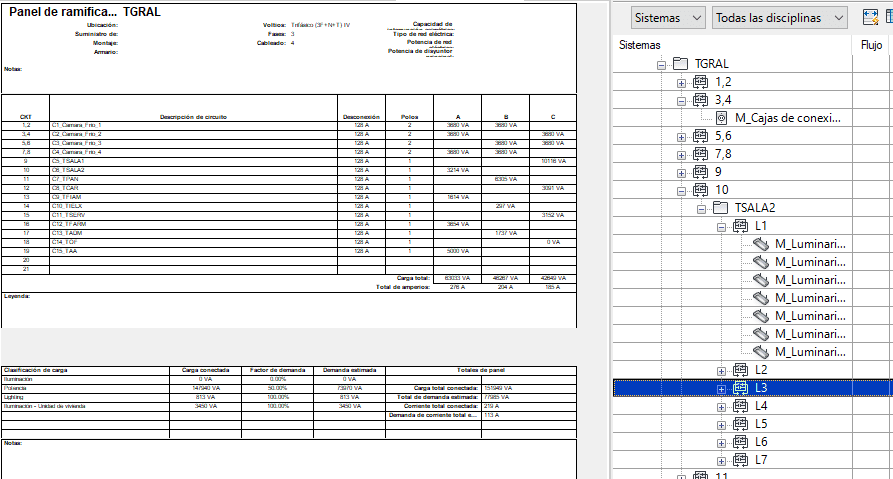
In the case of the Electrical Systems Model, In addition to modeling the trays, light fixtures, and electrical enclosures, the connections to the panels and their circuits were made as specified in the preliminary design. Once certain technical details are finalized, this allows for determining the load on the various panels and enables the balancing of their phases.
6. HVAC
In addition to these elements, several parameters were added to identify the lamps' brand, model number, installation date, and the date of the next maintenance.
In addition to assigning a unique code to all items—with a view toward a possible Operation and Maintenance Using BIM Methodologies, depending on the software, you may need to configure and export the data under the CoBie standard, designed for that purpose.
Information Management
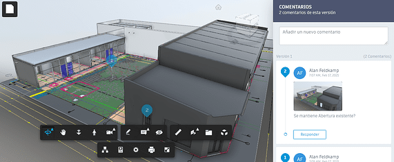
The Information Management Using BIM Methodologies It covers both the overall project workflow and the information contained in the various models.
At the level of the WORKFLOW We work with models that are independent by discipline yet linked to one another; communication with the tutor and consultations with the architect of the original project are conducted by uploading the models to the online platform. Autodesk Fusion Team, This allows users to view models through the web platform without needing specialized software; in addition to being able to add comments to specific objects in the model and track them, users can also view the various drawings uploaded to Revit from the platform, create sections, take measurements, and view the properties of elements.
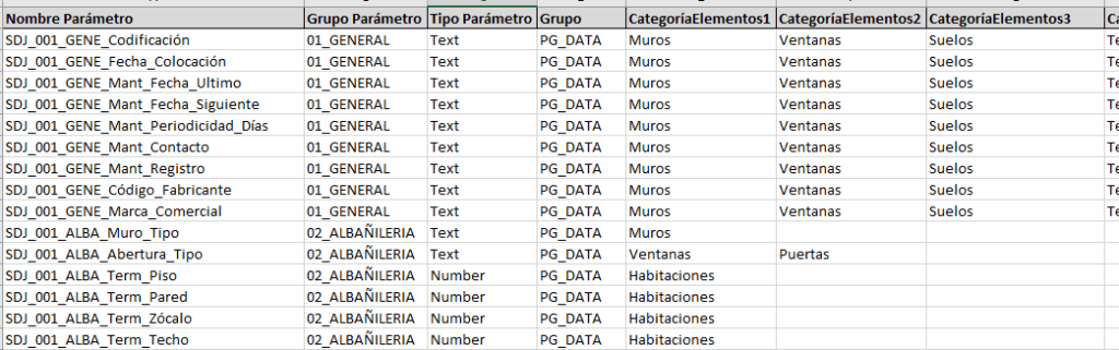
For the Model Information Management, among other things, we worked with visual programming DYNAMOTo automate tasks—in this case, using an Excel spreadsheet organized for that purpose and an existing shared parameter file—it creates the specified shared parameters and adds them to the Revit categories specified in the Excel file. The use of shared parameters is highly recommended for the efficient use of information, and in Revit, they can only be created and added one by one; once created, the name or properties of a parameter cannot be modified. so being able to automate a labor-intensive and repetitive task is a clear example of the advantages of working with these methodologies.
Organization of the Excel file from which to extract the data:
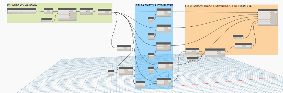
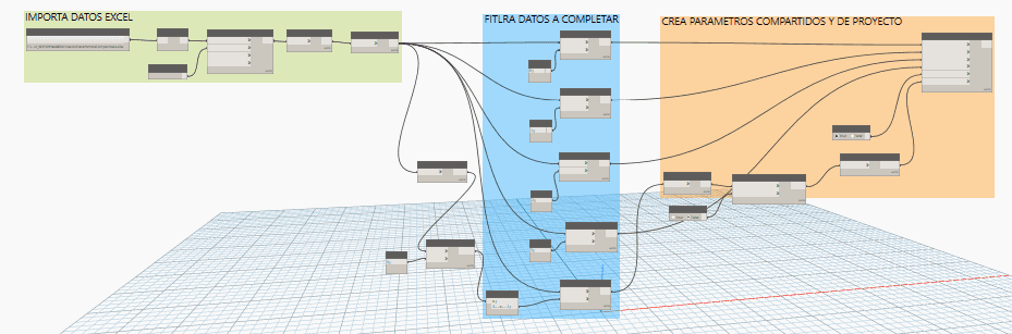
The first part of the routine is where you They load the data from Excell, the input data consists of an Excel file and the name of the Excel tab from which to retrieve the data (String), using the “List.RestOfItems”The first field in each list is removed—in this case, the titles—and with “”List.Transpose" The order of the lists is changed (from Excel rows to columns) so that it matches how they're organized in Excel. By default, it arranges the lists by rows rather than by columns in Excel, where the first list would contain all the titles we extracted using the previous node.
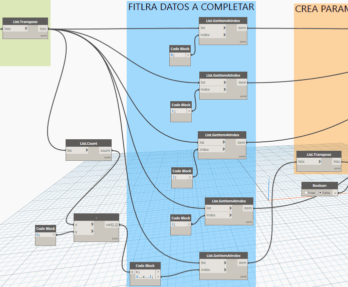
In the second part of the routine, they filter the data from each list with “”List.GetItemAtIndex", which allows you to separate the lists so they can be assigned independently to different nodes. Because of the way Excel is organized, the first list will be the Shared Parameter Name (index=0), the second will be the Shared Parameter Group (index=1), followed by the Parameter Type (index=2), the Group (index=3) where the parameter will be organized within the properties, and the rest are the categories to which each parameter will be assigned (Walls, Windows, Masses, etc.), in which case you need to ensure that the number of filled Excel cells for each parameter is taken into account to avoid errors, so with “List.Count” Count the number of filled cells in Excel, subtract 4 from that number (which represents the cells containing the previous data), and sort that list.
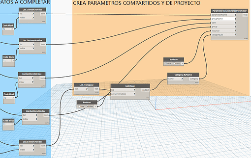
The last part is where shared parameters are created with the node “Parameter.CreateSharedParameter”, which also specifies whether the paraMeters will be either instance or type; in this case, it was assumed that all would be instance parameters. If you want to create some as type and others as instance, you should create another column in Excel with that information and filter it as you did with the previous ones.
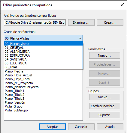
The result is that we can quickly compile a large number of shared parameters in an organized manner and avoid the error of transcribing them manually if we already have them listed.
Remember the differences between the types of parameters:
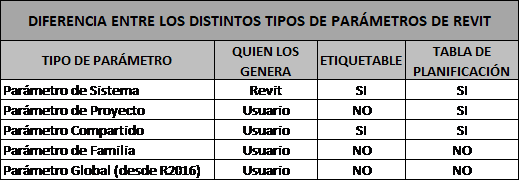
Therefore, it is recommended that work with shared parameters In order to make the best use of that information, and since it’s generated in an external file, it allows everyone working on the project to use the same parameters (It’s important not to duplicate this file; it must be on a network in a location accessible to Revit so that the file can be loaded and duplicate parameters can be avoided—ideally in the CDE).
After creating the parameters, when it comes time to fill in most of them with data, I use the BIM plug-in One (Excel Import/Export, bimone.com) that allows for two-way export of planning tables to Excel, making it possible to manage that information much more quickly—and even, we could involve third parties who are not familiar with BIM tools but who will provide us with the necessary data on specific equipment or facilities. This would enable a workflow where, for the As-Built Approval, the lists with blank fields—which we need to include in the model to ensure better Operation and Maintenance—are provided to the contractor and/or subcontractors, and they fill out the various Excel spreadsheets, without modifying the format, and then upload them directly into the model, thereby avoiding errors caused by data transfer.
To do this, each element of interest in the work must be identifiable by a parameter, preferably a code. This parameter, which I have called “Coding,” should clearly refer to the element and consist of an acronym that allows us to filter the data to locate it more easily.
Ideally, we should follow the criteria established in ISO 19650, which, with regard to naming conventions, currently sets forth the criteria for naming file containers and project files.
Rendering
Another common use of 3D models is its use for photorealistic rendering, even before the use of BIM methodologies, but these have made the process much more seamless and efficient, as various rendering software programs recognize the data for the elements, which allows for group them or manage them more effectively, as well as its materials and textures, while maintaining a link to the original files that allows changes to be made to the model without losing the progress made on the rendering. In this case, I used the program Twinmotion, because of its simplicity and excellent rendering capabilities, as well as the availability of student licenses, Twinmotion It has a good built-in library of materials, as well as elements, lights, animated characters, special effects, etc.
Another option—and one of the most powerful rendering programs for BIM workflows—is LUMION.
Collision Detection
One of the main objectives set for this project was to collision detection, Therefore, several disciplines were modeled, Masonry, Structural Work, Plumbing, Electrical Work, and Air Conditioning, and collision detection was performed among these.
To do this, the Navisworks Manager software, by directly linking the .rvt files, which generates cache files in the NWC, and the format used is NWF, which allows you to reload any changes made to the models without losing the work you've done.
Navisworks It's very powerful software, and so is its tool “Clash Detective”, which, in addition to performing static detection, can be linked to a timeline and a sequence to view potential collisions over time, in this case, only static detections were performed. An initial collision test was conducted involving all elements colliding with each other, resulting in more than a thousand collisions of all types.
This method is not recommended, since there are many collisions that, although detected as such in the model, are not actually collisions—for example, rooms with floors, pipes routed inside walls, small openings for utilities through walls, etc. Revit It allows for extreme levels of detail, but in general, it is not recommended.
In order to better manage interference, several collision tests were conducted, including:, Structure with Bathroom, Electrical work, Air Conditioning work, Plumbing, Electrical, and Air Conditioning work all at the same time, and some masonry work was performed detection of specific types of elements, such as doors and windows which is where there certainly shouldn't be any overlap with the other disciplines.
After conducting various tests, the collisions were grouped based on common elements; for example, the beams of the existing building’s facade wall were grouped with the downspouts, and the new foundations of the steel columns were grouped with the plumbing pipes, etc.
Another important point is that, once collisions have been detected, they must be processed, Navisworks It allows you to set statuses, as well as assign a person in charge and add comments, to track them.
Naviswork Collision Report
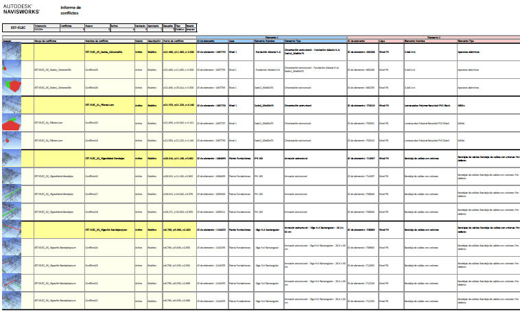
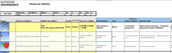
To quickly locate elements in Revit, you would use the element IDs of the clashes that are to be included in the clash reports and search for those elements using Revit's SELECT BY ID tool.
In Structuralia We would like to thank [name] for their outstanding work and initiative. Alan Feldkamp and his master's thesis project. Do you want to shape your professional future just like Alan? You can visit our Structuralia website and explore the wealth of educational resources in this field, as well as the variety of specialized master's programs you'll need to achieve your goals.
———–
AUTHOR'S REVIEW:
Alan Feldkamp Dall’Oglio:
Master's Degree in BIM Applied to Building Construction, offered by Structuralia and endorsed by the Isabel I International University in Spain. Architect with a degree from the University of the Republic of Uruguay (UdelaR).
Group member Organization of the BIM Forum Uruguay since 2018.
He currently works as a BIM modeler for the CCFC (Central Railroad Construction Consortium), a consortium of local and international companies formed to construct 273 km of railroad tracks, along with the associated infrastructure, and to provide subsequent maintenance.
An enthusiast of BIM methodologies, he continues to pursue training in areas such as Dynamo and BIM coordination, and is currently working toward Google’s professional Data Analyst certification in order to improve information management in BIM projects.
1. What would you highlight most about the master's program?
«The main thing I would highlight—and one of the key reasons why I chose this master's program—is the full text of the programmatic proposal, both in theory and in practice. In my case, I didn’t have much prior experience with various BIM software programs—just a somewhat basic knowledge of Revit—so I was interested in learning about BIM methodologies in general, but also to gain familiarity and hands-on experience with various BIM software programs and to learn best practices regarding their integration—where Revit is the primary software used, as it is one of the most widely used in the world within the construction industry— but we also learned to perform cost control in PREST and link it to Revit via COST-IT, model steel structures with TEKLA and link them to Revit, as well as design steel connections with DIAMONDS and POWERCONNECT, project coordination and clash detection with NAVISWORKS and TEKLA BIMsight, scheduling with SYNCHRO, as well as other topics such as programming with DYNAMO and visualization with LUMION, among others.
Among the activities carried out, one of the most notable was the implementation of a BIM execution plan by teams (BEP), using an actual bid for a subway station as a reference.»
2. How do you think this will help you in your professional development?
«I can assure you that it has already helped me—at first, by to explore BIM methodologies in greater depth, which has been emerging as a trend in the industry for some time now, but before the master's program, I only had a superficial understanding of what it entailed; I've come to realize that it's a vast and constantly evolving field in which I continue to learn and delve deeper.
Also for have experience with various software programs that are among the most widely used on the market, as well as sparking my interest in certain more specific topics, such as programming in DYNAMO, which led me to continue learning about the subject and which It was one of the factors that helped me land my current job, »as a BIM Modeler at the Central Railroad Construction Consortium."
3. Why did you choose Structuralia?
«When I decided to pursue a specialized master's degree in BIM, I evaluated various options; first and foremost, it had to be a 100% Online Training since there are no training programs in my country that cover the subject so thoroughly.
Among those possibilities, it had to be having a a very comprehensive program with a significant practical component, which, as I mentioned earlier, is one of the aspects I highlight about this master's program.
Also, the master's program should have a academic backing, which is due both to the professionals who participate as instructors and/or coordinators, and to the fact that it is one of the master's programs included among the Scholarships from the Organization of American States (OAS), an institution from which I received a partial scholarship that allowed me to pursue this master's degree.»