
This interesting TFM This guide, prepared by our alumnus Emilio Camino, explains how to approach a modeling strategy for road construction projects by proposing a modeling structure and testing the IFC's functionalities.
Master's Thesis Project: Modeling Strategy for Road Construction Projects
Today, the BIM methodology It has seen widespread adoption around the world and is even recognized as a key tool in national policies for the execution of public works projects, including those of construction as well as infrastructure. In this regard, there are countries that already consider it mandatory for the implementation of projects. However, this is not uniformly the case in all countries.
In Argentina, although there has been momentum since 2017 with the creation of the BIM Implementation System (SIBIM) and documents, pilot projects, and various adoption plans have been developed, BIM requirements are not yet included in either public or private tenders.
At Argentina's National Highway Administration—the government agency responsible for the construction and maintenance of all the country's highways—implementation began in 2020.
In the course of each of the case studies and pilot projects, it became clear that one of the key aspects of this type of infrastructure project lies in the modeling strategy.
In a road construction, Information from the model will often need to be transferred from one software application to another, and in many cases, there is no automated process for doing so. This highlights the importance of carefully planning the strategy to be used to avoid data loss or compatibility issues while the model is under development.
Furthermore, another key aspect for both public and private organizations is the ability to use open formats. This refers to the ability to use any brand when creating a model, as well as enabling the public sector to save on licensing costs by using open-source software, which are key factors in implementing BIM.
However, when it comes to road construction, as well as other infrastructure, these open formats are currently under development. This does not mean that we cannot work with what is already available, but rather that we should focus on and study in detail the existing possibilities.
Thus, this paper aims to address the two topics mentioned above by proposing aa modeling framework and checking IFC features for road construction projects.
Project Description
The assignment involves creating a preliminary design model for an urban road project in the city of Sarandí, Argentina, using BIM methodology.
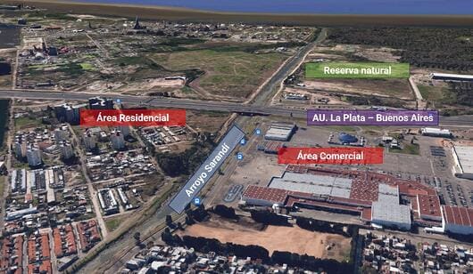
To that end, a bridge will be built to connect the roundabout in the commercial area to the residential area (yellow arrow), creating another roundabout on the opposite bank of the Sarandí Creek and connecting from there to the various city streets.
It is therefore proposed that create the digital terrain model, the various lanes and the roundabout, the overpass, as well as the cross-drainage works and signage, obtaining the quantity takeoffs from that model and preparing a simplified BEP explaining how the BIM model was created using the templates from SIBIM Argentina and, finally, generate the deliverables in IFC format, evaluating the capabilities of this format based on the progress made to date.
Preliminary Considerations
It is worth noting that, for this project, we had only one active license for a specific brand; therefore, all development was carried out using that company’s software.
That is why the conclusions and the validity of the proposal presented here are based on the possibilities offered by these programs.
However, there are others—which have different strengths and limitations and function differently—that must be analyzed in detail in order to develop an alternative modeling strategy and evaluate the functionalities of IFCs; however, this exceeds the scope of this paper.
Objectives and Scope
- Develop a preliminary urban road design using BIM methodology
- Propose a modeling strategy from the project's conception through the quantification of each construction item.
- Develop a simplified BEP that establishes the main modeling criteria, following the templates from the SIBIM of Argentina.
- Generate deliverables in IFC format and determine their current functionality for road construction projects.
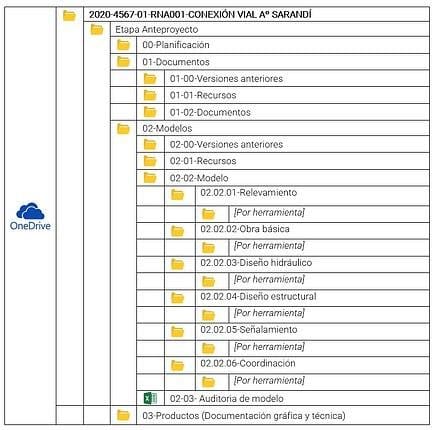
Definition of CDE
To begin the modeling process, OneDrive was designated as the shared data environment where all files will be stored, including those for archiving and communication.
This CDE will have a project designation as established in the BEP (2021-4567-01-AUA001-ROAD CONNECTION TO SARANDÍ).
The folder structure will be organized as follows:
Modeling Strategy
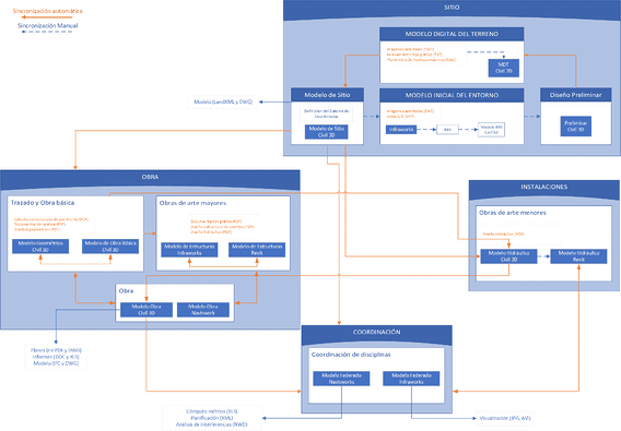
To create the project model, which involves everything from the digital elevation model up to the final metric calculations, the following strategy was defined, consisting of four modules: SITE, CONSTRUCTION, FACILITIES, AND COORDINATION.
Site Model
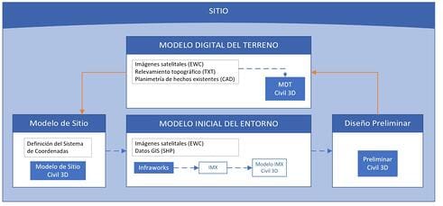
To create the site model, we began by defining the coordinate system in the Civil 3D and a study area was defined using polygons, which will then be used to generate the model of Infraworks.
Satellite images and raster data from the National Geographic Institute, as well as GIS data, were incorporated into this generated model, and the environment was developed and defined.
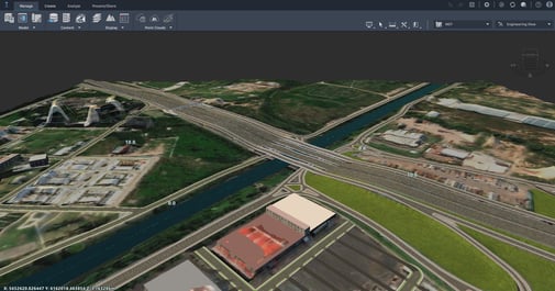
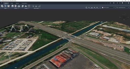
It was then imported into the Civil 3D, where the surfaces were adjusted and the topographic surveys were incorporated to ultimately produce the digital terrain model. In addition, satellite imagery and as-built plans were included.
Once the necessary corrections were made, the surface area, as well as the survey of the surrounding area, were incorporated into Infraworks, where the location of the project was finally determined. https://www.autodesk.com/latam/products/civil-3d/overview
Construction Model

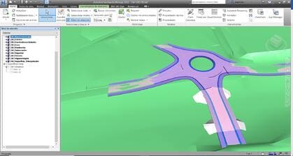
Starting on Digital Elevation Model and the environmental survey conducted in the site model were incorporated via a shortcut into a new file named Civil 3D, where the geometric design and basic construction of the roundabout were carried out.
To this end, and to avoid large file sizes, this task was divided into two parts: first, the geometric design model, in which the planimetric and altimetric data were defined; and second, the basic construction model, in which the pavement structures and standard profiles were determined.
All of these models were added to Infraworks, where, based on the composite roads, the bridge crossing the Sarandí Creek was defined. All preliminary sizing was performed there, minor modifications were made, and then the model was exported to IMX, where, using a plugin for Revit, we were able to finalize the design, incorporate additional information, and even define the structural framework.
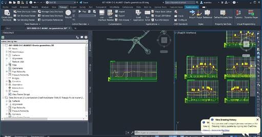
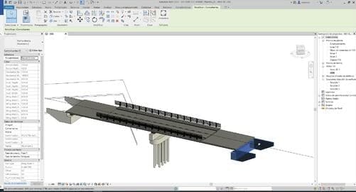
As for the coordination of all these models, it was carried out through Navisworks, as well as through Civil 3D, which includes all the major works of art listed in Revit, and it was verified that everything was correctly defined by performing interference analyses.
Construction Model:
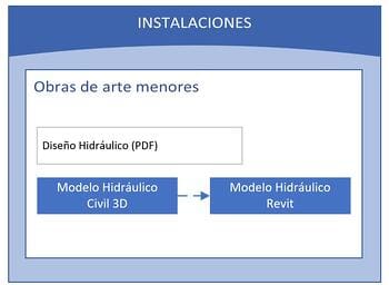
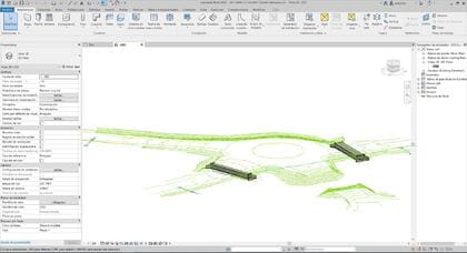
To model cross-drainage structures, the first step was to create the families corresponding to the types of culverts based on the standard drawings currently in use at the National Highway Administration.
To place them in their corresponding georeferenced space, the shared coordinates were used; to do this, a file was generated in Civil 3D, another file, in which their locations and the corresponding inlet and outlet elevations were defined.
Then in Revit, the coordinates were established, and the CAD file containing the aforementioned information was imported. The sewer line families were placed, each with its corresponding length and elevations.
Coordination Model:
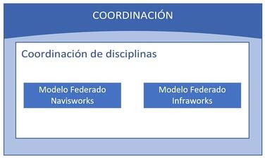
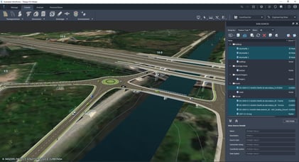
Finally, two coordination models with different functionalities are proposed. On the one hand, a Federated Model in Infraworks, which made it possible to handle all aspects of visuals and presentation, to create videos, and even to interoperate with GIS.
In this model, the digital terrain model, basic construction, and geometric design files were imported in .dwg format; the bridge was imported in .imx format; and the culverts were imported in .fbx format.
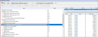
On the other hand, a Federated Model in Navisworks which made it possible to perform interference analysis and planning, as well as to generate the metric calculation.
BIM Execution Plan

Togetheror with the Modeling of the Urban Roundabout Project, The BIM Implementation Plan following the templates from SIBIM from Argentina.
This document provides an overview of the project’s key information, modeling details, reference information, all deliverables to be produced, the technology used, all aspects related to modeling, as well as a progress schedule.
For the purposes of this paper, we conducted the BEP analysis, addressing those fundamental aspects, particularly as they relate to the modeling strategy.
It is important to note that, as of today, the National Highway Administration does not yet have its own standards or guidelines, nor does it have any experience with this type of project.
In addition, the template used to prepare the BEP was designed for architectural projects; therefore, some adjustments had to be made to accommodate road construction projects, which have their own specific characteristics.
Open Exchange Format
Once the preliminary design was completed, the exporting the model coordination using the most widely used and most advanced open format for architectural works—that is, IFC.
The purpose of this project was to determine what export options are available and what its display capabilities are.
To do this, the first step was to export the alignments using IFC version 4×1, which supports this feature. However, after several attempts, we were unable to view them in IFC viewers.
The next step was to export the pavement structure in IFC 4×1, IFC 4, and IFC 2×3 formats. To do this, the first step was to generate Psets using the model data and convert that structure into 3D solids as shown in the image below.
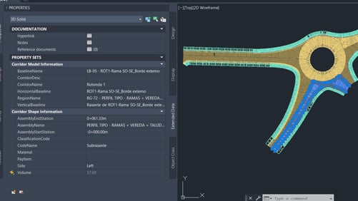
Then, by exporting to IFC in the Civil 3D, the different IFC versions (IFC 4×1, IFC 4, and IFC 2×3) were defined, and it was possible to set some general project parameters, such as author, company, and distribution, among others.
Finally, they began testing various programs to open the files to explore their potential uses.
The Importing that open format into IFC viewers It can be observed as follows:
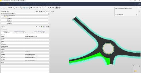
The display is correct; the configured Psets are visible and preserved, and the quantities of the various objects that make up the models are correctly included. However, the IFC Entity and Type could not be defined. These fields appear as "ifcBuildingelementProxy" and are left blank, respectively.
In the case of opening with Civil 3D, the display is correct; however, the 3D solid that was exported to IFC is being imported as Multi-View Block References. It is worth noting that it contains all the information set up previously.
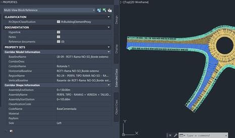
Attempts were made to open the file in other software programs such as Navisworks y Revit, but there were problems with the import that may have been caused by the project's coordinates. When the same project—but shifted to coordinates close to (0, 0, 0)—was imported (the software only accepts IFC 4 and earlier versions), the import was successful.
The main differences observed between IFC exports and Revit and with Civil 3D The difference is that the first one provides comprehensive support for the various IFC parameters, while the second one allows you to configure external information to be included in the file, but without distinguishing between the different IFC parameters. This means that when you open an IFC file generated in Revit work can continue and information can be added, while in Civil 3D The model must be rebuilt.
Conclusions
Currently, through a a concrete and systematic modeling strategy, detailed design documents for road construction projects can be prepared using automated processes and tasks, thereby minimizing errors in information transmission and errors resulting from manual tasks.
Furthermore, many of the best-known and most widely used tools worldwide are not designed for large-scale linear projects. However, by creating processes for well-standardized tasks They can be very useful and necessary, and serve as a great complement to those specifically developed for this type of project.
Finally, it should be noted that, although they are currently being developed for linear projects, the IFC are necessary, but not sufficient for creating project deliverables. These must be accompanied by other files, such as LandXML files, which provide information that cannot yet be incorporated into the former (alignments, MDT).
In this way, it would be possible to reconstruct the model, in addition to using it for the features detailed in the EIRs and BEPs, without relying on any specific software and without losing information necessary for each stage.
In Structuralia We would like to thank [name] for their outstanding work and initiative. Emilio Camino and his master's thesis project. Do you want to build your professional future just like Alan? You can visit our website at Structuralia and explore the extensive range of educational resources in this field, as well as the variety of specialized master's programs you'll need to achieve your goals.
———–
AUTHOR'S REVIEW:
 Emilio Camino is a civil engineer who graduated from the National University of La Plata. He recently completed the Master's Degree in BIM Applied to Civil Engineering”, taught by Structuralia, and is currently pursuing a master’s degree inUrban Engineering Planning and Management at the National University of Buenos Aires.
He works at the National Highway Administration, where he is part of the Studies and Projects Department and the BIM Implementation Team. His key responsibilities include: reviewing road projects in general; evaluating requests for construction or improvements submitted by other departments within the agency or by third parties; analyzing technical documentation and its specific and general specifications using specialized software; evaluating project alternatives; and implementing BIM methodology within the agency.
In addition, he is an active member of the BIM Forum Argentina and a member of the IRAM committee on “Building Information Modeling (BIM – ISO TC 59/SC13)”
AUTHOR'S STATEMENT:
1. What would you highlight most about the master's program?
«The most interesting points to highlight, now that the Master's Degree in “BIM Applied to Engineering” are the learning approach and the concept of BIM as a methodology rather than as software.
As for the learning experience, I felt very comfortable with the platform, which was highly interactive, and with the course content. In addition, the ability to work through the content at our own pace, guided by an overall schedule, allows those of us with heavy workloads to balance our studies with our jobs and gain training in what we’re passionate about.
On the other hand, the course is designed to help students understand the methodology and learn the best ways to work, rather than to teach them how to master one or more software programs—which, in my opinion, is the most important thing when tackling projects in one’s professional life.«
2. Do you think it will help you in your professional development?right?
« This master’s program has been very helpful for my professional development, as I am currently working on BIM implementation. Through the various courses, I have been able to gain knowledge and experience from the different instructors, which I can apply and use to learn from mistakes that have already been made elsewhere.«
3. Why did you choose Structuralia?
»After conducting “market research” on the various options—of which there are many—I noticed that Structuralia offered a very comprehensive academic program that focused not on software training but on understanding the methodology and its applications. Furthermore, the availability of various scholarships convinced me to choose Structuralia.".«