
This interesting master's thesis project explains the BIM Modeling for the Construction of a new access road to the beaches in the southern part of the island of Menorca.
Given the growing demand for BIM methodology in civil engineering projects, two years ago I decided to further my education by taking the Master's in BIM in Civil Engineering offered by Structuralia, where I completed my Master’s Thesis titled “BIM Modeling for the Construction of a New Access Road to the Southern Beaches of the Island of Menorca”, conducting an in-depth workflow analysis to design this linear project and evaluating the interoperability among available software programs.
This post describes the project's objective, the workflow followed, the software used, and the conclusions reached.
What was the objective of my master's thesis?
The goal of this project has been to analyze the workflow Steps to follow when carrying out a linear construction project, including the design of a bridge, and evaluating the interoperability among the various software programs available.
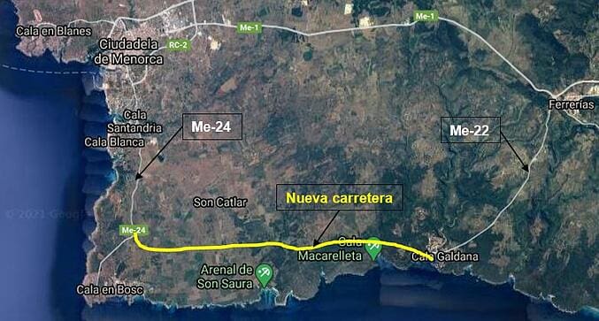
To that end, a New access road to the southern beaches of the island of Menorca connecting the Me-24 highway (between Ciudadela and Cala en Bosc) with the Me-22 highway (between Ferreries and Cala Galdana). Currently, access to the coves is via various roads branching off from the Me-1 highway, and there is no direct connection between the coves. In its final section, plans call for the construction of a bridge to cross a river valley. The Image 1 shows, in yellow, the road to be designed.
Workflow and Software Used
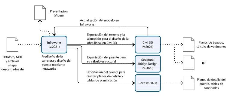
First, a preliminary road design and the bridge design using Infraworks software (v.2021). This program is designed for the field of pre-engineering and focuses on preliminary fit planning and analyzing the impact of infrastructure on the terrain. Its main uses include to provide information to support decision-making in the early stages of design. One of the drawbacks of this software is that the information it provides is not suitable for creating projects, although it does allow users to make important estimates to determine earthwork requirements and how they fit into the terrain.
Next, the following was used: AutoCAD Civil 3D (v. 2021) To adapt the road designed in Infraworks to Alignment Standard 3.1-IC, define the standard cross-section, and calculate the earthwork volumes.
For its part, the bridge was exported from Infraworks to Structural Bridge Design (v. 2020) for analyze the compatibility between the two software programs from which one could carry out the structural analysis of it. In turn, the following was used Revit (v. 2021) to create detailed drawings and scheduling tables for the bridge's components.
Preliminary highway design using Infraworks
As mentioned, the tool Infraworks was used for the conceptual design, thanks to its ability to quickly generate and analyze designs, terrain, and environmental characteristics.
As a preliminary step before creating the preliminary road design using Infraworks, the file was downloaded from the National Geographic Institute, the digital elevation model of the project area, the most up-to-date orthophoto of the PNOA and the shapefiles containing information on existing roads.
Next, a model was created in Infraworks (version 2021), and chose the coordinate system ETRS89.UTM-31N corresponding to the project area, and the files that had been previously downloaded from the IGN website were imported.
The next step was to design a road that would run close to the existing parking lots providing access to the southern coves, avoiding, whenever possible, crossing near existing buildings in the area. Once the design road was completed, it was converted into a composite road, and a bridge was built to span the elevation difference in a valley that had to be crossed.
Please note that in the 2018 version of Civil 3D the tool was available Bridge Module which made it easy to insert simple bridge models into the linear project. However, in the latest versions of C3D, this tool has not been further developed due to the introduction of Infraworks, which allows you to design bridges with different deck, buttress, pier, girder, and bridge support components. It is also worth noting that, in the latest version of Civil 3D (2021), bridges are incorporated as a new type of bridge object whose components are individual elements and are identified—a feature that was not present in the 2020 version, where bridges were imported as a single 3D object. Despite all this, bridges are not editable elements in any of these versions, so the bridge design was completed entirely in Infraworks.
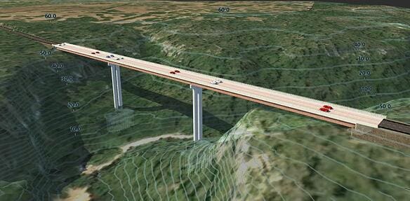
Once the model is complete, it They exported the .imx files for subsequent import into other software programs.
Road Design with Civil 3D
The design of the linear project was carried out using Civil 3D, version 2021, following the workflow shown in the Image 4.
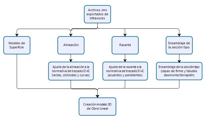
Using the same version of Civil as in Infraworks, both .imx files were imported.
The first issue to address is that the road was designed in Infraworks following the AASHTO standards As a result, the alignment was modified to comply with route specification 3.1-IC. To do so, the following steps were taken: by editing the imported lineup, generating a new alignment consisting of a sequence of straight lines, clothoids, and curves whose parameters comply with the alignment standards. Note that the Spanish standards file available for Civil 3D does not contain all the checks established by those standards, so Additional checks were carried out line-specific, curves or clotoids by creating styles. The same process was followed to adapt the grade to the alignment standard.
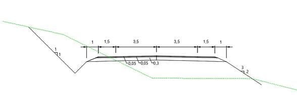
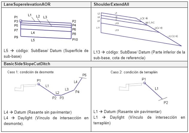
Regarding the standard section, the model imported from Infraworks was modified to match the cross-section shown in Figure 5, allowing us to create the various pavement layers and adjust the cut and fill slopes to the desired values. In Civil 3D, to design a standard cross-section for a linear project, an assembly object is first created, to which subassembly objects are added; once configured, these allow for the design of the desired standard cross-sections. The standard cross-section used in this project consists of the following subassemblies: Lanes 🡪 “LanersuperelevationAOR”, Shoulders and berms 🡪 “ShoulderExtendAll”, Slopes 🡪 “BasicSideSlopeCutDitch”.
Now that we have all the elements, we can Obtain the model of the linear structure. Linear design involves the use of the ground surface, alignments, profiles, and assemblies. The C3D tool manages the data by linking the assemblies to the alignment and the corresponding longitudinal profile.
A a linear composition consisting of several base lines and the intersection of the slopes with the surface was created by selecting the “natural terrain” surface as the target in the Create Linear Feature dialog box. To create the surface for the modified structure, we took into account that the project’s pavement package will begin at the natural ground level intersected by the top layer of our pavement package; therefore, a surface was created with the code of that line, which in our case is “datum” and is the same for all subassemblies. Finally, the outer contour where the linear structure intersects with the natural terrain, indicating the subassembly code for the slopes, which in this case was “intersection.”.
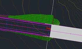
When importing the 3D model of the bridge from Infraworks, each component is represented as a non-editable 3D object; therefore, we can say that it serves only to visualize how the bridge fits into the project, since it does not interact with the linear structure. In other words, in the area where the bridge is located, the “target” surface is disabled for the linear alignment, and it does not recognize the bridge when creating transitions between the slopes at the abutments. To prevent the transition from the road to the bridge from being abrupt, The slopes were modeled using the following process:
- First of all, it is divided the linear work into regions, creating a transition zone before and after the bridge section that is approximately 40 m long, and a new standard cross-section was assigned without the slope subassembly. In addition, sThey removed the surface targets in this region and it reduced the frequency in this section, so that the transition would be generated more accurately.
- The transition region was isolated, and the following were extracted:, in this area, the characteristic lines of interest—that is, the lines that run along the subbase of the linear structure on the sides and at the abutment—were used as the basis for grading.
- Once the characteristic line has been obtained, using the grading tools, you generated a grading group and it created a leveled area with the natural terrain serving as the base surface of the volume.
- Finally, in the drop-down menu for the grading tools, you'll find selected “Clearing and Surface Earthwork,”, and once this option is selected, it selected the feature line created earlier. The grading was applied to the entire alignment using the same slopes as those used for the embankments and cuts in the linear project, yielding the result shown in the Image 7.
Exporting the Bridge to Structural Bridge Design
The 2021 version of Infraworks allows you to verify the structural strength of bridge girders. When the bridge is selected in the model and a girder line analysis is initiated, InfraWorks validates the initial composition of the bridge girders based on rules and compares the designs to the selected bridge design standards, including AASHTO LRFD, British, Australian, and Eurocodes. This allows the validity of the designs to be verified at a very early stage.
We have tested using this tool and then opening the results in the software Structural Bridge Design 2020. Note that the purpose of this project was not to perform a structural design of the bridge but rather to evaluate the interoperability between the various software programs available; therefore, the calculation was performed using the default loads provided by the program to verify the interoperability between the two software programs.
Change Management
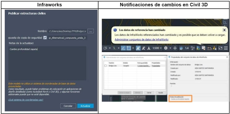
We analyzed what the process would be if modifications were made to the bridge model generated by Infraworks. First, we changed the depth where the footing was located, and the command “Publish Civil Structures” 🡪 “Update Existing in InfraWorks” was used to update the data for civil structures connected in Civil 3D (this would also apply to Revit).
When you open the model in Civil 3D, a notification appears indicating that the InfraWorks dataset has been modified and needs to be reloaded. When you select “Manage InfraWorks Datasets,” you’ll see comments about the changes made in InfraWorks and the option to update the modified file. When you reload the modified file from InfraWorks into Civil 3D, the model is dynamically updated; in this case, the footing depth is updated.
Exporting the bridge to Revit
Infraworks selected the bridge and chose the “Publish Civil Structures”. To open the generated .imx file from within Revit, the “” add-in was installed.“Revit InfraWorks Updater 2021”.
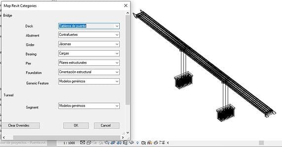
Next, created a new Revit project using the “Structural” template” and, for each component of the InfraWorks bridge, the Revit category to be assigned during the import process was configured (see Image 9). From the Add-Ins tab on the Revit ribbon, the “Import Civil Structures” option was selected by choosing the .imx file that had been previously generated in Infraworks.
Note that, despite having selected structural categories (structural columns, structural foundation, etc.) for importing the elements that make up the bridge, Revit does not recognize them as structural elements per se, and the “Enable Analytical Model” checkbox is not selected. Because of this, it is not possible to automatically generate an analytical model for subsequent export to a structural analysis program. One option would be to place structural elements at the locations of each imported element in order to generate an analytical model, but the problem with this solution is that, should any modifications be made to the model, the changes would have to be made manually in Revit.
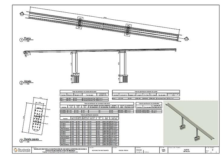
In addition, Revit has been used to create detailed drawings and planning tables of each of the structural elements that make up the bridge (see Figure 10).
Conclusions
The following is a summary of the conclusions drawn from the project:
- When designing a linear project with Civil 3D, it is important to note that the available Spanish code file does not include all design checks; therefore, it is necessary to perform additional checks specific to lines, curves, or clothoids by creating styles. This process can be somewhat tedious; therefore, for linear projects of considerable length, using Istram software is recommended, as it simplifies compliance checks.
- There is no specific module in Civil 3D for designing bridges or tunnels; therefore, to design these types of structures, you must use other software such as Infraworks or Revit.
- When importing the bridge into Revit, Revit does not recognize its components as structural elements per se, and the “Enable Analytical Model” checkbox is not selected. Because of this, it is not possible to automatically generate an analytical model for subsequent export to a structural analysis program. The way to do this automatically would be through Structural Bridge Design.
- Changes made in Infraworks are automatically updated in the various programs (in this case, Civil 3D and Revit), making it easy to keep the models up to date with the latest changes simply by reloading the imported file.
In Structuralia We would like to thank [name] for their outstanding work and initiative. Aida Santos Santamaría and his master's thesis project. Do you want to shape your professional future just like Alan? You can visit our Structuralia website and explore the wealth of educational resources in this field, as well as the variety of specialized master's programs you'll need to achieve your goals.
———–
AUTHOR'S REVIEW:
 Aida Santos Santamaría She holds a bachelor's degree in Civil and Regional Engineering, and holds a master’s degree in Civil, Canal, and Port Engineering from the Polytechnic University of Madrid, having completed the second year of her master’s program and her final thesis at the Swiss Federal Institute of Technology in Zurich (ETH). She speaks three languages: Spanish, English, and German. She recently completed the master’s program “BIM Applied to Civil Engineering,” offered by Structuralia.
For the past 6 years, he has been working at Geocontrol, where he is part of the Tunnels and Underground Works department. Among his key responsibilities is the execution of civil engineering projects related to underground works, both nationally and internationally. She actively participates in all design phases for both tunnels and the structures associated with these types of projects (walls, diaphragm walls, cut-and-cover tunnels, foundations, etc.). In addition, she currently serves as vice president of the youth group of the Spanish Association of Tunnels and Underground Works (AETOS).
AUTHOR'S STATEMENT:
1. What would you highlight most about the master's program?
«The master's program combines theory with practical exercises that help students apply the methodology they have learned using various software programs. This is very useful for their future application in the workplace.".«
2. How do you think this will help you in your professional development?
«For several years now, the use of BIM has been a requirement for engineering projects. Through this master’s program, I have gained a broad understanding of various areas (layout, structures, cost estimates, etc.) that will help me when tackling a project that requires the use of BIM." «
3. Why did you choose Structuralia?
»First, I was looking for a master's program that I could balance with a full-time job, and second, I wanted that program to focus specifically on civil engineering, since many of the master's programs currently offered are more focused on building construction.".«