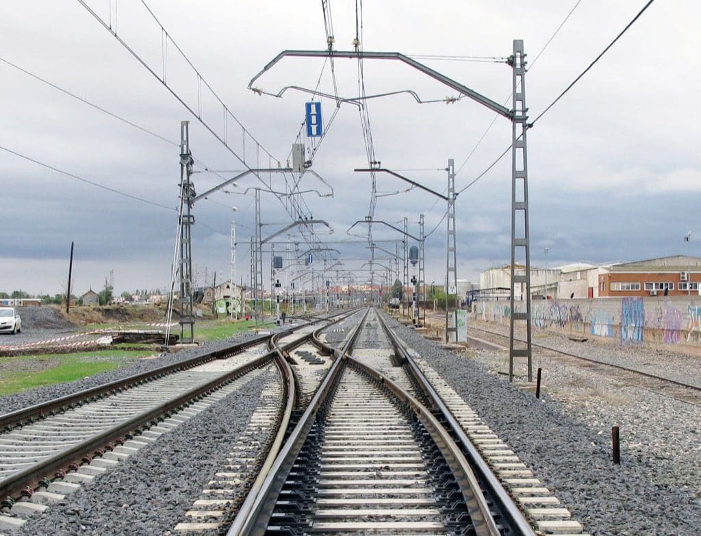
The electrification system supplies power to electric locomotives and is therefore essential to the operation of the line. The main power supply systems currently in use are divided into contact-based power collection systems (overhead contact line, third rail, and overhead conductor rail) and non-contact traction systems (magnetic levitation).

Of all these methods, the most commonly used is power supply via an overhead contact line, and that is the one we will focus on below.
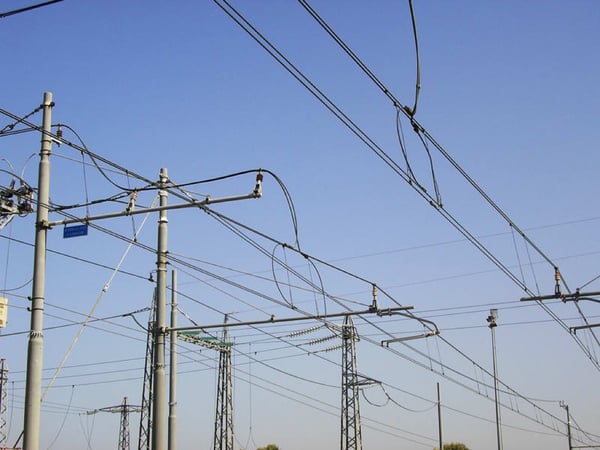
This system consists of the entire overhead wiring, including catenaries, contact wires, return wires, ground wires, lightning protection wires, line feeders, and booster feeders placed on top of supports, overhead conductor rails, foundations and structures, and support components.
Among the most common and significant issues Among the issues that arise on railway electrification lines, we can find the following:
- Failures in the line's insulation system
- Overdimensioned mechanical stresses in insulators
- Malfunctions in Antenna Surge Arresters
- Use of unsuitable parts or materials
- Broken or cut cables in the compensation system
- Pantograph Failure
The following outlines the standard procedures for resolving this type of issue.
Short circuit or break in insulators
To prevent these failures, it is necessary to perform periodic inspections, remove any dirt, and check for cracks. Before installing or replacing insulators, a thorough quality control check must be conducted to ensure the materials meet the required standards.
When the insulator breaks, the parts of the line it supports detach and fall onto the tracks where trains are running.
The procedure for repairing a fault caused by an insulator short circuit will vary depending on the insulator's location (anchor tail, fixed point, disconnect switch, or guyed assembly).
Malfunctions in Antenna Surge Arresters
In the event of a break in the arrester, to restore normal operation as soon as possible, it is necessary to cut or remove the cable connected to the catenary, leaving the arrester and the ground wires mounted on the bracket—provided they do not interfere with the clearance gauge—in a process taking less than five minutes.
The final repairs, including the replacement of the damaged parts, will be carried out during the time scheduled for maintenance operations.
If the connection between the arrester and the support is not very reliable (just a 95-square-millimeter cable, with one or two wire clamps), the support may break at the point where it connects to the cable leading to the arrester, causing the line to break, and it could even cause the cables to be run over by the first passing train.
Cutting the contact wire without winding it up
Contact wire breaks occur for the following reasons:
- Sudden lowering of the pantograph while the machine is drawing current
- Improperly Performed Contact Wire Splice
This type of fault is repaired by joining new contact wires using a connector, preferably a screw-type connector. When the break affects both wires, to avoid the localized concentration of mass caused by the connector for each wire, the connectors should be spaced approximately one meter apart. In this type of failure, it is often necessary to clean up the contact wires because they have been wrapped around by the pantograph or because there is a loss of material that may affect their resistance to mechanical tension, making it necessary to cut both wires, remove the damaged sections, and add the length of the cut wire.
The two ends of the contact wires shall be brought together using an appropriate tensioning device—such as a connection clamp, tensioning clamp, or sling suitable for the cross-section of the contact wires— taking care to secure the sling with one or two wire clamps if the contact wire is severely worn.
Non-wind-up lift wire cut
The break in the support cable occurs as a result of shunting in the antenna arresters, shunting in the suspension insulators, and a lack of connecting cables with sufficient cross-sectional area and in sufficient number between the support cable and the contact wires—that is, due to the use of non-equipotential hangers.
When this type of cable breaks, the catenary system fails. The repair is not complicated, as it simply involves cleaning up the cable—cutting off the damaged ends, replacing the length that was cut, and joining the ends using mass deformation splices.
The problem with this type of failure is that once the support wire has been severed, the tips may remain isolated from ground, and the contact wires may remain intact.
Inspecting damaged areas and replacing these components prevents this type of malfunction from occurring.
Failure involving tangled cables
In the event of a failure in the overhead wire system, there is a risk that the pantograph could cut the wires (support wires or contact wires), causing them to be run over by the train and other vehicles.
When this type of incident occurs, the train will have to be towed by diesel locomotives, and once that happens, repairs will be made to the track. Until the train is removed, maintenance crews will have to use:
- Move cables away from the track
- Check the condition of the pantograph
- Inspect brackets, suspension assemblies, contact wires, and the support for damage
- Remove the train using a diesel locomotive
The procedure followed to replace the damaged catenary is the same as that used to install a new catenary, but the installation may begin in the middle of the section, with the connection made using the appropriate splice, and the temporary suspension will be achieved using copper cable retainers.
Use of unsuitable parts or materials
For example, a pantograph may break after striking the tension arm due to screws coming loose or breaking because they are rusted, stripped, improperly tightened, etc.
The same approach would apply to the use of components or parts in applications other than those for which they are intended.
It is also important to use slings that are appropriate for the type of cable being joined, with the correct cross-section and type. If the cable’s cross-section has decreased, this sling cannot be used as if the cable were new. They should not be used if the cable is greasy or dirty; it must be cleaned first, and the installation instructions for these components must always be followed.
The steel cables used on the line must always be installed using the appropriate cable protectors, which prevent the cable strands from being cut and, consequently, the structure they support from coming loose.
Broken or cut cables in compensation equipment
A break caused by improper friction in the cable securing the line’s compensation conduits results in the catenary and the weights falling onto the track on the side where the cable breaks. On the opposite side, a variation occurs as the fixed point partially bears the line’s mechanical stresses.
Short-circuit detection systems detect these types of incidents and cause the power to be automatically shut off.
When repairing this type of malfunction, the first step is to determine whether the pulley can still be used and whether the necessary materials are available on site to repair or replace the damaged components. If the materials are available, the weights are lifted using the block and tackle, the pulley is secured, then the winch is positioned between the line and the pulley, and the line is reeled in until it returns to its original position. Next, the block supporting the weights is gradually loosened, and once the weights are bearing down on the pulley, the part securing the pulley is removed.
When the pulley has deteriorated or not all the steel cables needed for replacement are available, the pulley will be removed and the line will be secured directly to the pole without compensation. To do this, using a winch, block-and-tackle, or similar device, retrieve the entire line (contact wires and support wire) in one go, anchoring the entire set of cables to the same pole where they were previously located.
Pantograph Failure
A pantograph that is not in good working condition can cause problems with the catenary. The most common reasons why a pantograph can damage the catenary are:
- Excessively worn contact plates, caused by the continuous rubbing of the contact wires against the plates, leading to complete wear and tear, with the plates being cut through the center.
- Excessive pressure on the pantograph causes the contact wire to rise too high, wearing it down and increasing the risk to the pantograph as it passes over overhead switches. It also causes the pantograph arm to arch, bending its contact strips.
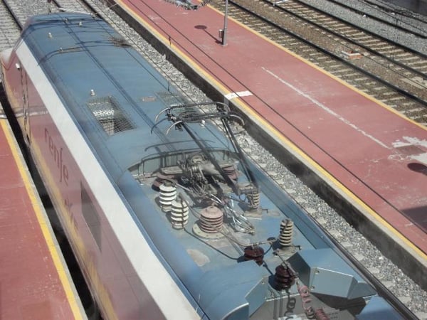
To prevent these incidents, pantographs must be inspected periodically, and any components found to be in poor condition must be replaced—particularly the contact strips, the contact surface, and the pressure with which the pantograph pushes against the track.
Check out our course:
Master's Degree in the Design, Construction, and Maintenance of Railway Infrastructure and Facilities