Can you find the Optimal Integration of BIM in Civil Engineering Projects? This interesting project TFM delves into the challenges and best practices for your project.
The demand for the use and application of BIM methodology, whether in design or on-site construction, is growing steadily on the part of the Government and Private Sector, and the world of Construction and architecture give us, as civil engineers, a clear advantage.
This advantage is reflected, on the one hand, in the limited maturity of the software civil engineering products available on the market and, on the other hand, in the technical staff and clients' knowledge of BIM methodology, who often lack an in-depth understanding of the many advantages of this new way of working. For these reasons, we find ourselves at a state-of-the-art stage of BIM in civil engineering, where advances in software and the needs or problems encountered by engineers they feed into each other, allowing both to grow, improve, and, ultimately, find the optimal application of BIM in civil engineering projects.
Although the factors affecting a building are specific, How much flexibility does BIM offer on a civil engineering project? And, specifically, how much leeway do you have in a linear work? We are operating in a much larger (or longer) space, with linear elements that may be kilometers apart and that, therefore, any modification to such an element affects numerous other elements—not only linearly but also in two and three dimensions—and these, in turn, have a significant impact on the landscape, the environment, society, and the economy.
The Advanced BIM Master's Degree in the Design and Construction of Linear Projects from Structuralia aims to address these issues. After completing this master's program, our alumnus Jordi Moliner He has taken it upon himself to tackle these issues in a linear art project as part of his Master's thesis, which he summarizes in this incredible article.
Master's Thesis, Andalusia–Murcia Railway Line, from PK 0+000 to 1+049.452, in Guadix, Province of Granada
The goal of the master's thesis is to demonstrate and apply a comprehensive vision and approach to the real-world problems encountered when tackle a civil engineering project (specifically, a linear structure), using BIM methodology.
The topics to be covered in the master's thesis are as follows:
- Development of a BEP
- Definition of the project phases
- Design and Planning of the linear construction project
- Presentation realistic assessment of the project
Scope of the Project
For this master's thesis, and in accordance with the guidelines and background information provided by Structuralia, the following has been addressed: Construction Project for the Andalusia–Murcia Railroad Line, from PK 0+000 to 1+049.452, in Guadix, Province of Granada, Spain.
Although the construction project revolves around this railroad line, within the scope of the project there is a urban area and a highway bypass. These two elements have not been developed at the construction design level, but they have have been taken into account when integrating the railroad line into the surrounding environment within theInfraworks model,which has helped to make better decisions throughout the project.
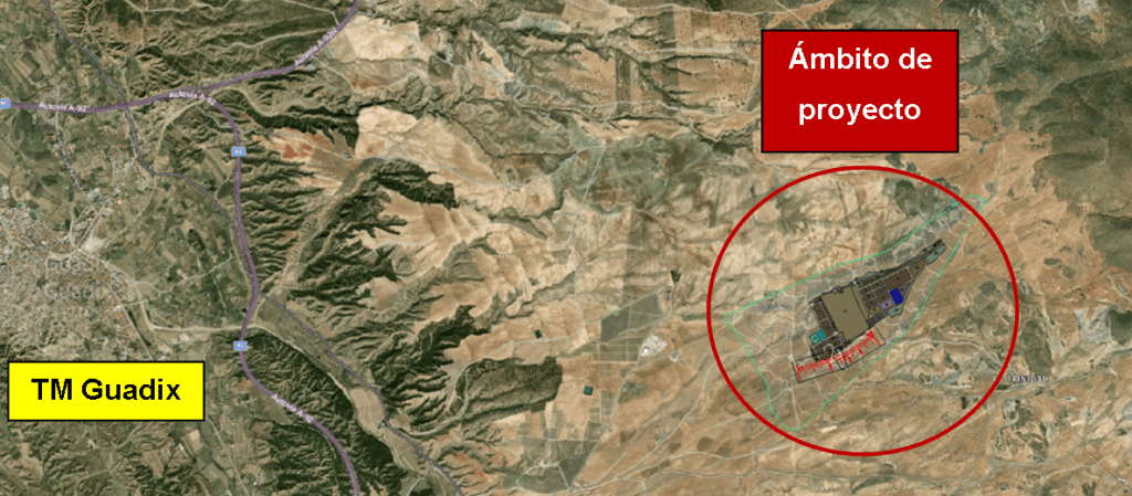
Figure 1. Project area of the new residential development. The A-92 highway is shown as it passes through Guadix, viewed in a plan-view orthophoto.
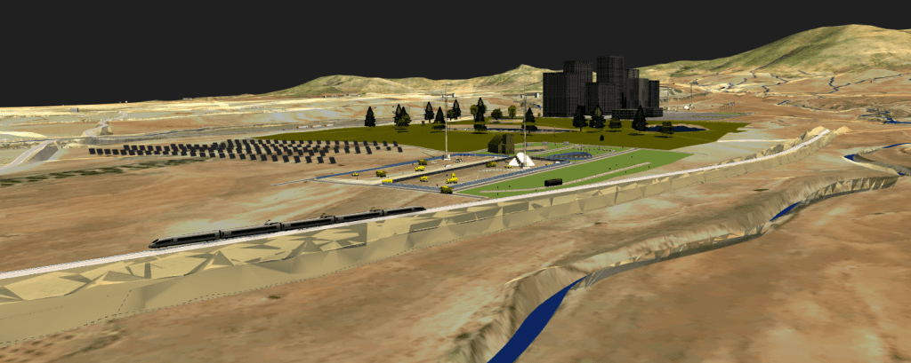
Figure 2. Project area of the new development. In the foreground is the proposed railroad line, and in the background is the highway bypass, all modeled in Infraworks.
Development of the BIM Execution Plan
The BIM Execution Plan (BEP) details the strategy for using BIM on the project, as well as the capabilities and competencies of the project design team to meet the client’s information requirements.
In the following sections, I outline the most important points of the BEP.
BIM Objectives and Uses
In accordance with the client’s guidelines, the overall objective of using BIM is to prevent critical changes in both the time allocated for each activity and the budget under which the service was contracted.
The specific objectives set during the project's implementation are:
1. Visualize the solution to facilitate the interpretation and communication of the project.
- Create more consistent drawings.
- Analyze the project's critical points and incidents.
- Identify and locate elements or materials within the building or infrastructure to make decisions.
2. Facilitate the tracking of the project's progress.
- Monitoring the project's progress.
- Evaluate whether the proposal is properly defined.
3. Facilitate the management of the completed infrastructure.
- Identify and locate the components or materials within the building or infrastructure.
Person in charge of each objective and BIM use
The BIM objectives and uses, as well as the required BIM deliverables, are assigned to one or more members of the drafting team, who are responsible for ensuring its quality and usefulness throughout the project design process. For this master’s thesis, my role would be that of BIM manager, as well as project coordinator, but I would have the support of specialists from each engineering discipline and modelers.
For some BIM objectives and applications, the following is also required: Participation and supervision by the client's technical staff.
BIM Deliverables
"BIM Deliverables" refers to all Documents and information required to obtain BIM models, as well as all products resulting from the use of BIM tools and workflows.
Collaboration Strategy and Shared Data Environment (CDE)
The CDE is based on the BIM 360 platform, since the software we will be using is from Autodesk.
Structuring BIM Models
All of the project's digital information will be organized into several BIM models, each with its own specific coding, such as:
The discipline models will be generated using the Civil 3D platform and AUTODESK REVIT 2022.
These models will contain all the necessary information regarding the modeled elements, their geometric details, and the information they contain, to ensure they are compatible with the uses defined in this BEP.
The models for each discipline will be integrated to form the federated coordination model, which will be referred to as the Federated Model. The project team will provide each validated discipline model in order to carry out the federation of models in accordance with the PEB. The BIM Manager will be responsible for generating and maintaining the Federated Model.
The Federated Model will consist of the various discipline models in IFC format; these files will be federated on the NAVISWORKS MANAGE 2022 platform and can be viewed on the platform NAVISWORKS FREEDOM 2016 or higher. In addition, the IFC files themselves will be available individually, so that any stakeholder can federate the files that make up the federated model on any platform or IFC viewer.
Reference coordinates
To ensure that the layout of elements is consistent across the different models when creating the Federated Model, all models must have identical coordinates in their BIM space.
Two UTM coordinates in the ETRS89 system must be defined, corresponding to the X, Y, and Z axes, which will serve as a common link between the models, with georeferenced baselines obtained from the planned topographic survey.
Parametric content of the model
Levels of Information (LOI) are divided into 4 groups:
- LAW 1: Deliverables for Basic Projects.
- LOI 2: Deliverables for Detailed Design Projects.
- LOI 3: Deliverable upon Project Completion (As-Built).
- LOI 4: Deliverable under the Operation and Maintenance model.
LOI 2 will be used in this project.
Information Quality Assurance Plan (IQAP)
To ensure the quality of the information entered into the model and to produce final deliverables containing reliable information, internal model quality checks will be performed, primarily by the BIM Manager and modelers.
Defining the Project Phases
Once the BEP has been developed, it is advisable to define the project’s drafting phases, which are as follows:
- Conceptual design.
- Detailed design.
- Property Sets and Solid Generation.
- Export the model.
These phases are addressed throughout the design of the linear construction project, as detailed below.
Design of a Linear Construction Project
Conceptual Design
The project area is defined by the statement from the master's thesis itself, as it might be provided by the client of the project or construction work in question.
The selected runner has a low environmental and urban impact, with few or no services affected and avoiding any intersections with other road infrastructure or waterways that might require large viaducts. Nor does it interfere with the current urban development of the town center. The bypass runs on the other side of the town center, parallel to the railroad.
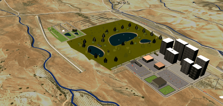
Figure 3. Location of the rail corridor. Infraworks helps analyze the available space, as well as the impact on other infrastructure and urban areas. It also assesses interference with urban services and waterways.
Detail Design
The topographic data provided by Structuralia was used, as it offered a sufficient level of detail to develop the detailed design. Based on this topographic data, a surface withCivil 3Don which the railway route will be designed.
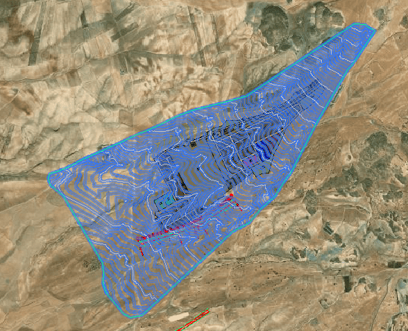
Figure 4. “EG” (Existing Ground) TIN surface created from the provided topographic data.
- Regulations: The current regulations of ADIF, taking into account maximum values under normal and exceptional conditions.
- Design speed: In accordance with the client's guidelines, the design speed is 120 km/h. The minimum speed for verifying insufficient superelevation is limited to 80 km/h.
These speeds would be possible, provided that certain route requirements are met based on parameters such as topography, the degree of urbanization, and other factors, the operation of both passenger and freight trains.
- Urban and industrial development plan for the area, provided by Structuralia.
- Presence of buildings or industrial facilities.
- Road and rail infrastructure in the area.
- Presence of protected environmental areas.
- Presence of public waterways.
The horizontal alignment consists of straight sections, a clotoid (L = 160 m), and a curve (R = 800 m).
The superelevation has been limited to 140 mm on the curve with a radius of 800 meters; the 160-meter-long clothoids ensure a smooth transition in superelevation.
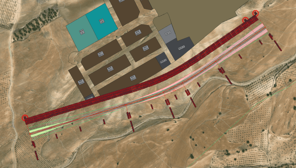
Figure 5. Plan view of the railroad route.
- Elevation drawing: The longitudinal gradient is limited to 1.5% (i.e., 15 thousandths), so that both passenger and freight trains can operate on the line.
It could have been raised to 25 thousandths to reduce earthwork, since the terrain is rugged, but It was decided to keep it at 15 thousandths to allow both trains to operate.
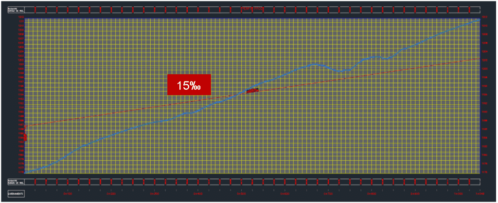
Figure 6. Elevation of the railway alignment, with a constant gradient of 15 thousandths. The alignment is shown in red, and the natural terrain is shown in blue.
- Other factors: The maximum cutting height is 9 meters, while the maximum embankment height is 11 meters. These are considerable heights, but they are also found in other railway projects in the country that have already been completed.
No sidings or stations have been planned; therefore, the need to verify any aspects of the alignment related to track equipment, turnouts, switches, spikes, etc., has not been analyzed. The design of the station for this urban center could be a future line of work to be developed in another master’s thesis related to BIM methodology, but it falls outside the scope of this thesis.
Since there are no intersections with other linear structures or developed areas, and since there are no tunnels, no regulations or specifications regarding clearance have been considered.
- Section type: A standard railway cross-section was designed using Civil 3D's SubAssembly Composer tool, incorporating the most common railway components in accordance with the guidelines and dimensions requested by the client, such as:
- Train, ties, and rails.
- Ballast, subballast, and subgrade.
- Pipes.
- Earthwork and clearing.
- Roadside ditches.
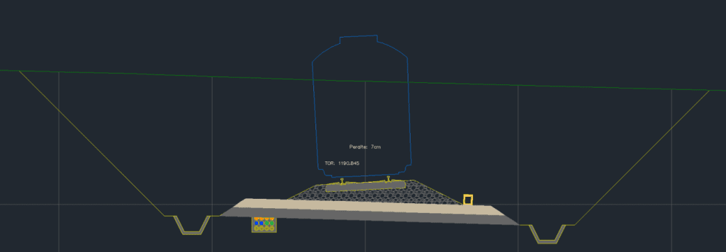
Figure 7. Cross-section showing longitudinal drainage elements and channels, generated using SubAssembly Composer.
- Linear work: Once all the layout elements for the plan, elevation, and section were collected, the linear alignment (corridor) was determined.
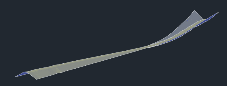
Figure 8. View of the linear feature in the Civil 3D Object Viewer.
According to the client's specifications, due to the terrain and the need for tunnels on other sections of the line, this line is designed as the first line powered by rechargeable batteries at both the origin and destination, so there is no need to electrify the line or install the associated overhead wire.
- Signage and Communications
The installation of cable trays and signal and communications prisms is planned for the railway-type section.
No urban utilities have been identified within the project area; therefore, there is no need to disrupt any utilities or plan for their replacement.
The necessary code has been designed and programmed using Civil 3D's SubAssembly Composer for each of the volumes, areas, and lengths of the various elements that make up the cross-section, in order to automatically obtain the measurements of each of those elements.
The floor plans, profiles, and cross-sections have been obtained.
Property Sets and Solid Generation
Each of the elements that make up the standard section has been assigned a set of properties, or property sets (PSETs).
Computer-generated properties (such as the volume of sub-ballast) provide the most useful information and can be easily updated if changes are made to the project.
Unfortunately, Civil 3D only allows you to obtain machined volumes, so for rail lines or pipelines—where it is useful to know the length, you must configure the calculation of that data using formulas, which typically involve dividing the volume that Civil 3D calculates automatically by the rail or pipeline cross-section, which must be entered by the user.
Once the model solids have been generated, the machined PSETs can be viewed.
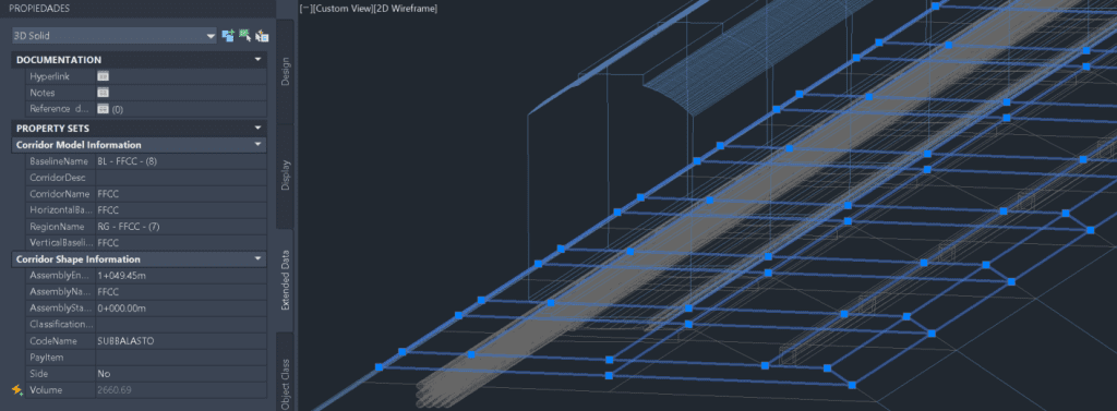
Figure 9. Volume is one of the PSETs associated with the SUBBALASTO solid, which enables automated, intelligent measurement that is updated with every change to the model.
Exporting the Model
Export to Navisworks
All the information generated by Civil 3D has been exported to Navisworks, and a construction plan has been generated for each of the imported elements. This construction plan allows each solid to be associated with a task, so that you can view the partial progress of the project and the solids based on the completed tasks associated with those solids.
Navisworks brings together information such as PSETs, construction drawings, 3D visualizations, and clashes. If structures or other elements had been designed in other software, such as Revit, it would have been possible to import them into Navisworks to view them together.
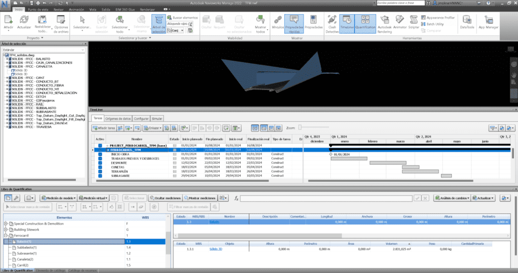
Figure 10. View of the model imported into Navisworks with the construction schedule.
The model has also been exported to IFC so that it can be viewed using the various free viewers available on the market. In this case, the chosen viewer isBIMcollab.
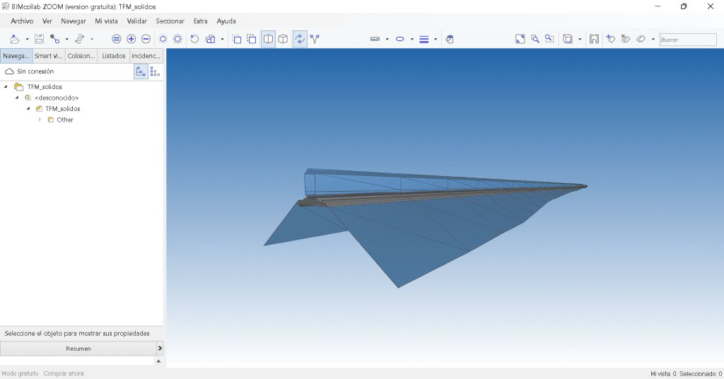
Figure 11. View of the model in the IFC viewer.
Realistic presentation of the project
In order to create the presentation video for the linear project, the model was also exported to Infraworks, where the developed area and the highway bypass were also modeled.
Infraworks is user-friendly software that delivers results that are highly effective both conceptually and aesthetically, allowing you to fully capitalize on an idea for commercial purposes and client presentations, as well as to analyze conceptual designs.
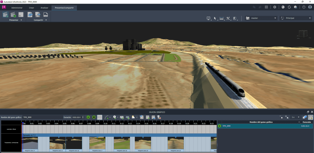
Figure 12. Still image from the presentation video created using Infraworks.
Conclusions
I think the Master's Degree It equips students to begin developing and applying BIM methodology both individually and as part of their work teams, replacing traditional work methods with an approach that is initially more complex but ultimately yields very positive results.
My master's thesis has been key to my ability to carry out a linear construction project using BIM on my own, from start to finish, all the way through final delivery to the client.
The BIM software currently available on the market allows us to take design to a higher level of analysis. However, I believe that, although there has been significant progress in recent years, all BIM stakeholders (consulting firms, construction companies, government agencies, private entities, etc.)—and especially those in the fields of civil engineering and linear infrastructure projects—still have a long way to go.

Author's Review
Jordi Moliner Martínez He holds a bachelor’s degree in Civil Engineering and a master’s degree in Civil Engineering (Roads, Canals, and Ports) from the Polytechnic University of Catalonia. During his university studies, he participated in exchange programs at the École Spéciale des Travaux Publics (Paris) and Tongji University (Shanghai). He speaks Spanish, Catalan, English (C1), and French (B2). He recently completed the Advanced BIM Master's Degree in the Design and Construction of Linear Projects at Structuralia and is currently pursuing a master's degree in Artificial Intelligence Applied to Engineering and Architecture.
In 2018, he joined Meta Engineering as a Civil Engineering Project Engineer, and in 2021 he assumed the position of Director of the Civil Engineering Projects and Studies Department in the company's International Division.
He leads a team of about 20 people at Meta Engineering’s office in Mexico, and in addition to overseeing the technical, financial, commercial, and human resources management of the division, he manages complex projects related to railways, highways, and urban development in countries such as Mexico, Spain, Panama, and Costa Rica.
Author's Testimony
1. Why did you choose Structuralia?
«Mainly because of the content this Master's Degree »In particular, it doesn't just cover the knowledge needed to be a BIM Manager, but also delves into the use of each design software program, highlighting the real challenges associated with each one and offering a comprehensive overview of what it means to work with BIM methodology in civil engineering projects."
2. What would you highlight most about the master's program?
«The level of knowledge provided by each of the modules and the wide range of software made available to students: Civil 3D, Navisworks, Infraworks, Synchro, Presto, Dynamo…"«
3. How has it helped you, or how do you think it could help you, in your current or future professional development?
«To understand how BIM works on linear construction projects, its potential, and its limitations, so that I can adopt it on an individual basis and—step by step—integrate it into Meta Engineering’s international civil engineering team.".«